Radio frequency (RF) PCB and microwave PCBs can be found in wireless products from handheld devices for medical and industrial applications to telecommunications systems for base stations, radar, and global positioning systems.
The most important thing for producing radio frequency PCBs is controlling the signals using (i) material types and material characteristics (loss tangent / Df and dielectric constant / Dk) (ii) low profile copper foils (iii) weave styles and (iv) how we layout the copper circuitry, as all these factors have a significant impact on the performance of the finished product.
At Pandawill Circuits, we have a wide range of laminates for your choices.
● RO3003: Dk of 3.00 +/- .04
● RO4003C: Dk of 3.38 +/- 0.05
● RO4350B: Dk of 3.48 +/- 0.05
● FR408HR: Dk of 3.68, tg190
● FR408: Dk of 3.67, tg180
● TU-872 LK: Dk of 3.8
● TU-872 SLK Sp: Dk of 3.5
And more available

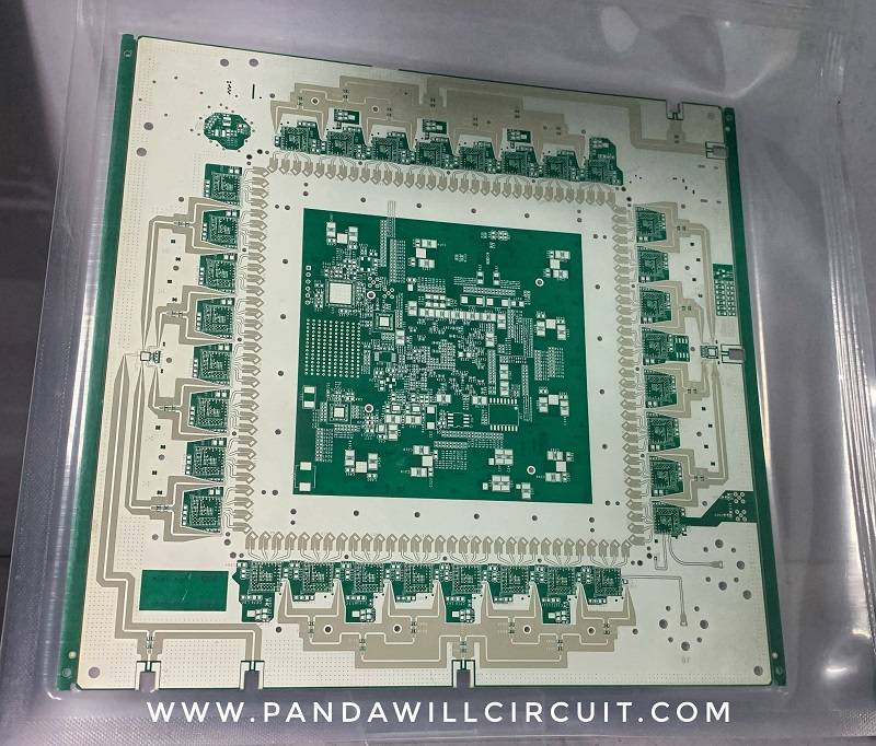
10 layer Material: Rogers RO3003; board thickness 1.6MM, Surface finish: Immersion silver
Application: 5G wireless infrastructure

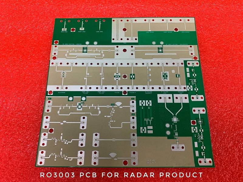
2 layer Material: RO3003, board thickness: 0.4mm thickness, surface finish: immersion silver

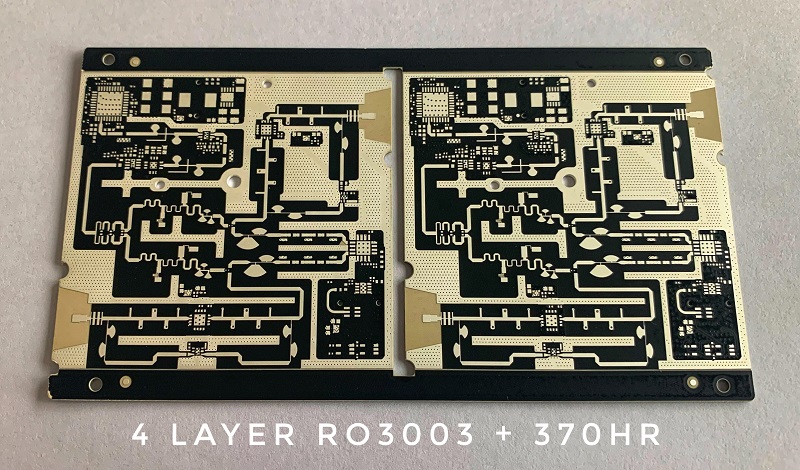
4 layer, Material: 1-2 layer RO3003 + 3-4 layer Isola 370HR, board thickness 1.6MM
Surface finish: Immersion silver
Radio Frequency PCB – Technical specification
| Number of layers | 2-20 layers |
| Materials | Low loss / low Dk, higher performance FR-4 |
| Board thickness | 0.2-3.0MM |
| Max PCB size | 580*1000 MM |
| Copper thickness | 0.5-4 OZ |
| Minimum trace | 0.075mm |
| Surface finishes | HASL LF, OSP, ENIG, Immersion silver |
| Technology highlights | Controlled impedance, low loss materials; Hybrid or Mixed Dielectric Boards, etc |
Pandawill Circuit has been manufacturing RF PCB for telecom, medical, industrial application for over 10 years. Please contact us if you need further information or assistance, we are happy to help you.
